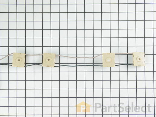
Spark Igniter Switches and Harness Assembly
$
131.87
In Stock
Get this part fast! Average delivery time for in-stock parts via standard shipping: 1.8 days.
PartSelect Number PS2004065
Manufacturer Part Number 12002790
Manufactured by
Whirlpool

Check if this fits your product and find model diagrams
Need help finding your model number?
Product Description
Spark Igniter Switches and Harness Assembly Specifications
This includes the 4 ignition switches and wire harness.

How Buying OEM Parts Can Save You Time and Money
Troubleshooting
This part fixes the following symptoms:
Will Not Start
This part works with the following products:
Range.
This part works with the following products:
Maytag, Jenn-Air.
Part# 12002790 replaces these:
AP4010264, 1203540, 12002790, 74009455, W10136714
Questions and Answers
Be the first to ask our experts a question about this part!
✖
Ask a Question
Ask our experts a question on this part and we'll respond as soon as we can.
Something went wrong. Please try again later.
Your Question Has Been Submitted!
Our experts will send you an email as soon as your question has been answered.
Customer Repair Stories
Average Repair Rating: 1.8 / 5.0, 2 reviews.
What's this?
- < Prev
- 1
- Next >
Sort by:
Search filter:
Clear Filter
Your search term must have 3 or more characters.
Keep searches simple. Use keywords, e.g. "leaking", "pump", "broken" or "fit".
Sorry, we couldn't find any existing installation instruction that matched.
Ignitor switches shorted out
The ignitor switches are installed on top of the 4 gas valves for the range top. These switches control the electronic ignition. To replace the switch assembly the top of the range must be removed to gain access.
This was made more difficult by the fact that the screws that hold the burners to the range top were rusted and had to be drilled out so the the burners could be released from the top.
1. Disconnect the power to the range.
2. Open the top oven door.
3. Remove 2 - 1/4" sheet metal screws at the front corners of the range top assy. Remove the Burner knobs and the two Phillps screws that holds the gas valve assembly to the range top.
4. With a drill, remove the tops of the screws to release the burners from the range top. If the screws are in good condition and just unscrew them and the upper burners from the Orifice Holders. (I had to replace the orifice holders because the screws were stuck in them due to rust).
5. When the burners are free, lift the range top at the front and remove it from the range. Disconnect the ignitor wires from the ignitors on each holder.
6. To replace the Orifice Holders, disconnect the gas supply pipes from each holder by loosening the compression nut at the holder using an adjustable wrench. Secure the Orifice Holders when loosening the fittings, BE CAREFUL not to damage the aluminum gas supply pipes.
7. Note that there are 3 different Holders, be sure to use the holder that matches the specific location.
8. For LP gas fueled ranges ONLY, remove the small gas jets from the old holders and install them in place of the parts supplied with the new orifice holders. The new parts contain NATURAL GAS jets which are not compatible with LP gas. Each Different Orifice Holder uses a specific orifice or jet, make certain that the orifice matches the orifice holder. Check for leaks at the gas connections using soapy water.
9. Carefully raise the old ignitor switches (4) off the shafts of the gas valves. Note the top and bottom configuration of the switches
10. Carefully release the wires that come from the rear of the range from the rearmost switch. Press a suitable pin or other suitable tool in a the hole, beside the wire, just enough to release the wire. (Look at the NEW switch assemble to see how this works). Remove the wires from the NEW switch first to see how it is done. Repeat the process on the old switches. (you will re-use the wires that come up from the rear of the range.
11. Install the new switch assembly over the four (4) burner gas valves, take care to align the "D" shaped shafts with the holes in each valve.
12. Insert the wires in the two connections on the rearmost switch. CAUTION!!! Be sure to install the wires so that the color codes agree with the wires on the new switch assembly. Black to black and gray to gray.
13. Install the 4 clear plastic "shields" over the shafts and against the top of each switch.
14. Re-connect the ignitor wires to the burners and Re-Install the range top, in the reverse order of dis-assembly.
Other Parts Used:
-
Michael from Dardanelle, AR
-
Difficulty Level:Difficult
-
Total Repair Time:More than 2 hours
-
Tools:Pliers, Screw drivers, Socket set, Wrench (Adjustable), Wrench set
39 of 45 people
found this instruction helpful.
Was this instruction helpful to you?
Thank you for voting!
Replace 2 ignitors and 1 ignitor switch
I must admit that I did not do this. A neighbor who has electical experience did the job.
The screws that hold the ignitors were too corroded to reuse. It required drilling new holes and taping threads. If self-taping screws were included it would be easier to replace.
The switch was much easier to replace with flare nut wrenches.
The screws that hold the ignitors were too corroded to reuse. It required drilling new holes and taping threads. If self-taping screws were included it would be easier to replace.
The switch was much easier to replace with flare nut wrenches.
Other Parts Used:
-
Dorothy from Branford, CT
-
Difficulty Level:A Bit Difficult
-
Total Repair Time:More than 2 hours
-
Tools:Screw drivers
12 of 16 people
found this instruction helpful.
Was this instruction helpful to you?
Thank you for voting!
- < Prev
- 1
- Next >
Customer Reviews
Filter By Rating:
- < Prev
- 1
- Next >
Sort by:
Search filter:
Clear Filter
Your search term must have 3 or more characters.
Keep searches simple. Use keywords, e.g. "leaking", "pump", "broken" or "fit".
Sorry, we couldn't find any existing reviews that matched. Try using some different or simpler keywords.
Marlena M - April 29, 2019
Verified Purchase
May Tag Stovetop Burner Igniter Wiring Harness
The stove is 15 years old and still in good shape. I was glad the part was still available and it was made exactly the same as the old part, came undamaged and fit back in perfectly. We were glad that we didn't have to buy a new stove!
Nicholas K - June 28, 2018
Verified Purchase
Easy Repair, Defective Part
The part arrived quickly but one of the 4 switches was broken. The central part did not articulate within the outer portion, so one of the igniters is still broken.

July 6, 2018
Hello ,
Thank you for leaving a review on the . Sorry it had taken us so long to get back to you. We have been a bit more popular then normal and are now able to check our reviews.
I’m sorry to hear you had that experience. We would like the opportunity to fix this situation. I will be sending you an email shortly. Look forward to hearing from you!
- < Prev
- 1
- Next >
Model Cross Reference
This part works with the following models:
PartSelect Number: PS2004065
Manufacturer Part Number: 12002790
Brand
Model Number
Description