Magic Chef Parts
Find your part
Enter your model number or a part number and click "Search"
Popular Magic Chef Parts
Your Price
$7.44
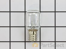
Light Bulb - 40W
PartSelect Number PS884734
Manufacturer Part Number 8009
This an authentic OEM 40-Watt replacement light bulb, used in a number of household appliances. It is specially designed to withstand extreme temperatures, which is why these replacement bulbs are most often used to light the inside of refrigerators and ranges. It features a standard socket base, which means you simply unscrew the burnt-out bulb and screw in the replacement. Depending on the appliance you may require a screwdriver or nut driver to access the light bulb. We recommend you wear work gloves while handling this replacement part. It is constructed of glass and metal and is sold individually. Depending on the appliance and location of the bulb within it, you may want to consider disconnecting power and using a flashlight for easier access to unscrewing and re-screwing in your bulb during this repair.
Installation Instructions
judie from mays landing, NJ
interior drawers were off their rollers
pulled the washer out and replaces the top roller system on both sides and the replaced the weels and brackets on the bottom drwaer. however i had trouble putting the dish washer back correctly and had to call a repairman to adjust the dishwasher and alighn it to open and close properly. but i did do good inside. i feel it was easy and a success. thank you for having the supplies for us to attempt to repair it on our own.
Read more...
Your Price
$16.60
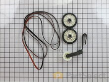
Multi Rib Belt - 92-1/4"
PartSelect Number PS346995
Manufacturer Part Number 341241
This dryer drum belt (Whirlpool Dryer Belt, Drive Belt) has four ridges, three grooves and is 1/4" wide, and 92 1/4 inches in length. It comes in black and is made of rubber. The belt transfers the rotation of the motor to turn the drum. The belt attaches to the drum, idler pulley, and motor pulley.
Fixes these symptoms
- Heat stays on after drum has stopped
- No heat or not enough heat
- Noisy
- See more...
Installation Instructions
Ray from Denton, TX
Dryer tub belt broke
Removed the two screws that attatch the lent channel to the top of the dryer, then lifted the top of the dryer by pushing in on the two locking tabs located at the front , left and right , corners of the dryer top with a small flat head screw driver. The top of the dryer will fold back out of the way. At this point I removed the two 1/4 inch screws that are located on the inside of the dryer front left and right corners that hold the front panel/door to the two side panels. Now I was able to lift the front panel up and set it to the side. The bottom of the front panel that contains the dryer door that I just removed was held on the bottom by two clips that slide into slots on the front panel and did not require any removal to disconnect the bottom of the front panel, just pull up on the front panel. Since the tub was held in place by floating on a seal at the back of the dryer and a seal on the front panel , which I just removed the tub is now free floating except for the two alignment roller wheels at the bottom of the tub. It is easier if you lay the dryer on its back at this point with front of the tub pointing up. I pulled the tub out and cleaned the years of built up lent and removed all the pieces of the old , destroyed, belt. Note, the belt tentioner is located at the front of the motor which on the bottom right hand side. If your belt is broke like mine the tensioner may/will fall to the back of the dryer when you tilt it back, but do not worry. Once the dryer was cleaned up I put the tub back in place , still on its back and made sure the two alignment rollers were in place and rolled freely when the tub was turned by hand. Another note, my original belt tensioner did not have a rolling wheel that the belt rode on , but was a semi-circle smooth surface that the belt remained in constant friction with when the dyer was running, so I made sure the replacement tensioner I ordered with my new belt did have a rolling wheel that the belt would ride on, which I believe will reduce wear and extend the belt life. The new belt came with a diagram of the belt and tensioner routing which was helpful. Note: do not take the tensioner wheel off/apart when trying to route the belt. Follow the instructions routing diagram. The tensioner is held in palce by inserting the bottom back half into the slot in the bottom floor of the dryer making sure it is aligned with the belt pully on the shaft of the dryer motor. The dryer is still on its back side. Now, it was easier for me to route the belt around the center of the tub, following the marks from the original belt, and hold in in place in a few spots with masking tape and then route it thru the tensioner and onto the front pully of the motor. Make sure you have the grooves of the belt against the tub and the grooves are aligned with the pully on the motor. Now you can remove the masking tape that was holding the belt around the tub and spin the tub by hand watching the belt making sure it is not in a bind and is traveling around the motor pully , tensioner and tub freely. Make sure the tub is still sealed on the back side wall. As you turn the tub by hand you can adjust the belt by hand so that is following the original marks around the tub left by the orignal belt. Also double check the two alingment rollers and make sure they are spinning and on track. Now put the front panel with the door on by sliding it onto the two clips that are one the bottom at each side and put the two screws in that hold the front panel to the two side panels. Now stand the dryer back up and spin the tub by hand again making sure it has a good seal on the back side and on the front panel. Pull the top back down and put the two screws in that hold the lent channle to the top. I am not sure when the belt started failing on my dryer, but was amazed at how quiet it runs now. Guess I was use to the extra noise made by a dryer that was about to die. This was a cheap and easy repair and glad I did it myself.
Read more...
Your Price
$2.72
Chrome Drip Bowl - 8 inch
. Read more...
PartSelect Number PS11750107
Manufacturer Part Number WPW10196405
This manufacturer-certified drip bowl is also known as a drip pan, and it is designed for use with cooktops and ranges. It sits below 8-inch burner elements and catches drips and spills from the cookware on the burner. The diameter of the drip bowl is approximately 10 inches. This replacement might appear slightly different, but it will fit your appliance. You will need no tools to complete this repair. Simply remove the burner element, remove the old bowl, line up the hole on the new bowl with the terminal block and drop it into place. Make sure the bowl is flat before reinstalling the element. While you have the element out you should inspect the terminals for corrosion, damage, or discolouration. If you notice any of those things you should also replace the element and terminal block. You will need to replace your drip bowl if it is lost, damaged, or can no longer be cleaned. This replacement part is sold individually. To extend the life of your new drip bowl we recommend you clean it regularly with soap and water. We recommend only using the recommended drip bowl for your appliance; generic versions will not fit properly which could affect the performance of your elements and cause long-term damage.
Fixes these symptoms
- Element will not heat
- See more...
Installation Instructions
Joe from Greeley, CO
oven wouldn't heat
First I removed the two screws that hold the element in place. I then pulled the element out about 3 inches and disconnected the two wires, then removed element and replaced with new. Read more...
Your Price
$30.55
Refrigerator Door Switch
PartSelect Number PS12728638
Manufacturer Part Number W11384469
Door switch turns the light off when you close the door.
Fixes these symptoms
- Light not working
- See more...
Installation Instructions
Clint from Rayville, MO
Lights inside refrigerator not working
I used a flat-head screwdriver to pop out the old light rocker switch. Then, I unplugged the wires, plugged them into the new light rocker switch, and then popped the new switch into the hole. That's it! Lights began working again.
Read more...
Your Price
$5.16
Drip Bowl - 6 Inch
. Read more...
PartSelect Number PS11750108
Manufacturer Part Number WPW10196406
This drip bowl is used for electric cooktops and ranges, it is designed to sit under a 6-inch surface burner. It catches the drips and spills coming from the cookware on the surface burner. This drip bowl is chrome, and it has a diameter of 8 inches. You need to remove the burner element to replace this part. Line the hole up with the element terminal blocks, and ensure the new bowl is flush with the surface of the cooktop before replacing the burner element. Drip bowls need to be replaced when they are lost, damaged, or you are no longer able to clean them adequately. This replacement part is sold individually.
Fixes these symptoms
- Element will not heat
- See more...
Installation Instructions
Joe from Greeley, CO
oven wouldn't heat
First I removed the two screws that hold the element in place. I then pulled the element out about 3 inches and disconnected the two wires, then removed element and replaced with new. Read more...
Your Price
$55.82
Flat Style Oven Igniter Kit
PartSelect Number PS1573892
Manufacturer Part Number 12400035
The flat style oven igniter kit is used in gas ovens and ranges. It is what provides the heat needed to open the gas valve, and it ignites fuel for the burner assembly. This part can be used for both bake and broil elements, and it can replace both short and long igniters. However, it cannot replace round style oven igniters. If your igniter glows for 90 seconds or more without igniting the burner, this means it is too weak to open the valve. The element in your igniter may have shorted it and it might not glow at all, or it might only glow orange or red. It needs to glow white hot; if it cannot get hot enough the gas will not be released from the safety valve and it will be impossible to light the burner in your oven. This kit includes the igniter, ceramic wire nuts, an insulation pad, a metal bracket, a variety of plug ends, and an instruction sheet. The body length is 3 3/4 inches, and the element inside is approximately 1 1/2 inches. This replacement part has an amperage range of 3.3 to 3.6. The element inside this igniter is extremely fragile, do not touch it. Before you start repairing your oven or range, make sure you have unplugged it and shut off the gas supply.
Fixes these symptoms
- Element will not heat
- Gas igniter glows, but will not light
- Gas smell
- See more...
Installation Instructions
James from Ferndale, MI
Oven would not work but the Broiler did
The oven had been working intermittently for a while and after repeated threats of starvation from my spouse I finally took a look even though it was summer and the grill was working fine. The Igniter would glow red when the oven was turned on but the gas would not flow to it no matter what the temperature setting. I searched online and found this site that explained it was possible for the igniter to glow but if it was not drawing the correct amperage (because its resistance was too high) then the main brain would not allow the gas valve to open. So I took a look at the broiler and it had the same igniter. I measure the resistance of both of them and the oven igniters resistance was higher (don't rememeber the reading) then I moved the Igniter from the broiler to the oven and the oven worked from there it was just a matter of ordering the part. End of story except for I am still doing all the cooking on the barbecue outside.
Read more...
Your Price
$134.42
Replacement Ice Maker
Unplug appliance.
Remove timer cover by hand pressure @ edge.
Remove single attachment screw & bracket at lower front of icemaker.
Disconnect wiring harness from socket @ rear of compartment.
Tricky part was determining what type of connection held the other two attachment points along the long edge of the icemaker. I did not have repair manual or useful drawing but looked @ PartsDirect pic of side brackets & used a small mirror to confirm that mine were also some sort of "snap in" attachment.
Remove icemaker unit by pushing upward and outward on the unit. I takes a good bit of pressure and will pop loose, but be careful not to break attachment bracket from freezer wall.
Scavenge shut off bar and wiring harness from old icemaker once you have it out & attach to new one before installing it back in freezer.
Again, you might find a mirror useful to align those pesky snap-in brackets with the new unit.
Since you probably kept your freezer running while waiting for the part, the plastic snap-ins will be cold and brittle. I warmed them up first by applying a dampened cloth heated in the microwave to make them a little more pliable.
A good push of the new unit towards the snap-ins along with some upward force will get it stable.
Reattach the metal screw in bracket & connect the wiring harness to rear plug... and don't forget to plug the whole thing back in.
It will take awhile for the first batch of cubes dump as the timer may need to cycle completely around to get to the fill cycle... be patient.
Dump the first couple of batches of cubes just to make sure you're free of any residue. Read more...
PartSelect Number PS2121513
Manufacturer Part Number D7824706Q
This ice maker (Ice Maker Assembly, Refrigerator Ice Maker) produces ice cubes that are ejected into the storage bucket. It is located in the freezer section of your appliance, mounted on the freezer wall. The ice maker can break from normal wear and accidental damage. If this happens, your refrigerator may no longer make ice cubes, or may not make enough cubes, and the part should be replaced. This model measures approximately 11 inches long and 5 inches wide. It’s constructed of plastic and metal, and comes in black/white/silver. This assembly includes the ice mold and the control device.
Fixes these symptoms
- Clicking sound
- Doesn’t stop running
- Ice maker dispenses too little ice
- See more...
Installation Instructions
Bernie from Diamond Bar, CA
Icemaker producing few or no cubes and often leaving "kling-ons" on ice tray
Interior surface of ice tray felt rough & flaky (coating deteriorated) so cubes would not release.Unplug appliance.
Remove timer cover by hand pressure @ edge.
Remove single attachment screw & bracket at lower front of icemaker.
Disconnect wiring harness from socket @ rear of compartment.
Tricky part was determining what type of connection held the other two attachment points along the long edge of the icemaker. I did not have repair manual or useful drawing but looked @ PartsDirect pic of side brackets & used a small mirror to confirm that mine were also some sort of "snap in" attachment.
Remove icemaker unit by pushing upward and outward on the unit. I takes a good bit of pressure and will pop loose, but be careful not to break attachment bracket from freezer wall.
Scavenge shut off bar and wiring harness from old icemaker once you have it out & attach to new one before installing it back in freezer.
Again, you might find a mirror useful to align those pesky snap-in brackets with the new unit.
Since you probably kept your freezer running while waiting for the part, the plastic snap-ins will be cold and brittle. I warmed them up first by applying a dampened cloth heated in the microwave to make them a little more pliable.
A good push of the new unit towards the snap-ins along with some upward force will get it stable.
Reattach the metal screw in bracket & connect the wiring harness to rear plug... and don't forget to plug the whole thing back in.
It will take awhile for the first batch of cubes dump as the timer may need to cycle completely around to get to the fill cycle... be patient.
Dump the first couple of batches of cubes just to make sure you're free of any residue. Read more...
Your Price
$8.56
Light Bulb - 40W
The filters are very easy to replace. No tools needed.
Hope this helps. Read more...
PartSelect Number PS2376034
Manufacturer Part Number 8206232A
This 40w light bulb is a replacement bulb constructed of glass and metal. It is an easy-to-install electrical part which produces 40w of light. If the bulb won't light up then it may be broken and should be replaced. The bulb attaches directly to an appropriate light socket and has a small screw-in base. To access the exterior light bulb, you will need to remove the panel on the bottom of the microwave using a Phillips screwdriver. If your exterior light bulb has not been changed before, it is probably held in place with some silicone. You will need to cut away this silicone to remove the old bulb. If you cannot access the silicone with a utility knife, it can be removed using dental floss. Once the silicone is removed, simply unscrew the old bulb, and replace it with the new one. Be sure to disconnect the power to the microwave before you begin this repair. This light bulb measures about 1 1/8 inches. We do not recommend using a higher-wattage bulb for this appliance, and can only recommend this specific bulb. If fixing the bulb does not solve your microwave light issue, it's possibly a problem with the socket, which means the socket and/or board will need to be replaced. This can be a more dangerous repair, so consult your user manual or a technician before attempting.
Installation Instructions
Chris from Cedar Hill, TX
Burned out light under microwave and Filters needed changing
I just removed the multiple screws which held the hood cover on. I then attempted to remove the light bulbs from the socket. This proved impossible because the bulbs were so fragile from the heat and grease build up. To make this task much easier and probably safer, just replace the bulb housing and light bulb. The bulb housing unplugs very easily. Just replace it then screw your new bulb in. P.S. Be sure to unplug appliance before you start.The filters are very easy to replace. No tools needed.
Hope this helps. Read more...
Your Price
$55.36
Condenser Fan Motor Kit
Removed the screws holding the back panel.
Removed the fan blade.
removed 3 screws holding the condenser fan.
Remove the 3 metal brackets attached to the fan.
(First note which studs the brackets are attached to. Attach the 3 metal brackets to the new fan. (New screws were supplied)
Cut and strip the wire about two inches from the fan.
Cut and strip the new wire. I cut the new wire in half (about 6 inches.) Connect the two wires, twist and used 2 wire nuts. Tie wrap the wire to the wire harness. Mount the new fan (three screws)
Screw the back panel back on.
Mount the new Read more...
PartSelect Number PS395284
Manufacturer Part Number 833697
This condenser fan motor kit is designed for use with refrigerators. This fan draws air through the condenser coils and over the compressor. It does this with the goal of cooling the warm refrigerant before it enters the evaporator. When your fan or fan motor is not working your refrigerator will not cool properly. This is a 2-Watt, 115 Volt motor that rotates the fan in a counter clockwise direction. This kit includes the hardware needed for installation, and a set of instructions. Before you begin any repair work make sure to unplug your appliance.
Fixes these symptoms
- Freezer section too warm
- Fridge and Freezer are too warm
- Fridge runs too long
- See more...
Installation Instructions
Tom from Franklin, WI
Sometimes the condenser fan would start causing the refrigerator to overheat.
Unplug the appliance.Removed the screws holding the back panel.
Removed the fan blade.
removed 3 screws holding the condenser fan.
Remove the 3 metal brackets attached to the fan.
(First note which studs the brackets are attached to. Attach the 3 metal brackets to the new fan. (New screws were supplied)
Cut and strip the wire about two inches from the fan.
Cut and strip the new wire. I cut the new wire in half (about 6 inches.) Connect the two wires, twist and used 2 wire nuts. Tie wrap the wire to the wire harness. Mount the new fan (three screws)
Screw the back panel back on.
Mount the new Read more...
Your Price
$29.84
M Series New Style Coil Kit
2. Removed two bolts at bottom front of machine and took off the bottom front panel.
3. Removed three bolts from black plastic exit vent and took it out to give more room to access everything.
4. removed two wires and screws on the limit thermostat. Did the reverse to place the new one.
5. Removed wires (remembering placement), then holder screw. rotated the Gas Dryer Sensor counter clockwise to release the bottom tab so the sensor can be taken off the flame tube. Did the reverse to place the new one on.
6. Removed the one screw on the gas/flame tube that holds the bracket and igniter inside the flame tube. Removed the wires fro the igniter (remember placement) Slid the whole assembly toward the back of the machine to get the tube off the gas valve then rotated the whole assembly counter-clocwise to release the tab on the left side of the bracket. This was a little tight and had to work with it a bit to get the tab out and slide the whole piece out of the flame tube.
7. Once the tube and igniter were out i removed the scree that holds the igniter and replaced with the new one. Made sure no dust, etc. was in the piece.
8. Did the reverse to place the tube/igniter back into the flame tube.
9. Carefully and forcefully removed the wire connectors to the two coils. These were tough to get off. Removed the two screws that hold the bracket that holds the two coils in place. Slid the coils off the spindles remembering which one has the two wire connection and which one has the three wire connection and the way they went on. Replaced the old with the new. Placed the bracket onto the new coils and made sure the little bumps on the top are in the holes in the bracket. Tightened the screws to hold the coil bracket. Reattached the wire connectors to the coils making sure they go ALL the way back on.
10. Vaccumed everything I could to get lint, dust, etc. out.
11.Replaced the black vent plastic.
12 Made sure the exit vent on the back was not crimped or clogged. Checked the little flap door where the vent goes outside to make sure it opens and closes super easy to no air flow is restricted.
13. For testing I left the bottom panel open. Make sure you closed the door, reconnect the plug and turn the gas valve back on. Hit the go button on autodry or timed dry. The door must be closed to create the closed circulation of the system so the fan sucks the flame into the tube otherwise the flame will not fire deep into the tube and will set off one fo the overheat sensors. After hitting the go button your drum will start to rotate, then a few seconds later you'll hear a click and your igniter will start to burn bright orange. Another click and the gas should flow and ignite.
14. This shows that you've fixed the ignition problem. I just replaced everything I thought that could be wrong in stead of hunting and trial and error. All the parts were about $137 so I thought it was worth making sure.
15. IMPORTANT: If during your test the flame turns off after a little while then turns back on only to turn off again, don't panic. This happened to me as well. I found that you need to run the dryer with wet clothes in the dryer. The wetness in the clothes will keep the autodry sensor from shutting off the dryer since there will be moisture in the exhaust. If it's on timed dry the wet clothes will cool the exhaust air and keep the overheat sensors from turning the heat off. So no heating of dry clothes to get out wrinkles. Just dry the wet clothes. This is all I did and it's been working great so far. Good Luck! Read more...
PartSelect Number PS334310
Manufacturer Part Number 279834
When the igniter reaches a high enough temperature, these coils (Coil Valve, Dryer Gas Valve Coil Kit, Dryer Valve Coil Kit, Gas Valve Solenoid) work together to open the gas valve and allow the gas to enter the burner. This is a safety mechanism to ensure that there are no unsafe buildups of gas inside your appliance. The coils are attached to the dryer gas valve. If the dryer does not heat or heats intermittently, the coil may not be opening the gas valve. Both coils must be operational for the valve to open. No continuity would indicate a defective coil, but they can be intermittent and fail when they get hot. Both coils should be replaced when one of them is broken. This part can break as a result of material fatigue from normal use. This part measures approximately 1 inch in diameter and 1 inch in height, and is constructed of plastic and metal. It comes in black/beige. This part features a 3-terminal boost/hold coil and a 2-terminal secondary coil
Fixes these symptoms
- No heat or not enough heat
- Noisy
- Shuts off too soon
- See more...
Installation Instructions
Michael from Kirkwood, MO
Gas Dryer would not ignite
1. Removed lint screen and holder frame. Unplugged the electrical cord and closed the gas valve in the line before it goes into the dryer.2. Removed two bolts at bottom front of machine and took off the bottom front panel.
3. Removed three bolts from black plastic exit vent and took it out to give more room to access everything.
4. removed two wires and screws on the limit thermostat. Did the reverse to place the new one.
5. Removed wires (remembering placement), then holder screw. rotated the Gas Dryer Sensor counter clockwise to release the bottom tab so the sensor can be taken off the flame tube. Did the reverse to place the new one on.
6. Removed the one screw on the gas/flame tube that holds the bracket and igniter inside the flame tube. Removed the wires fro the igniter (remember placement) Slid the whole assembly toward the back of the machine to get the tube off the gas valve then rotated the whole assembly counter-clocwise to release the tab on the left side of the bracket. This was a little tight and had to work with it a bit to get the tab out and slide the whole piece out of the flame tube.
7. Once the tube and igniter were out i removed the scree that holds the igniter and replaced with the new one. Made sure no dust, etc. was in the piece.
8. Did the reverse to place the tube/igniter back into the flame tube.
9. Carefully and forcefully removed the wire connectors to the two coils. These were tough to get off. Removed the two screws that hold the bracket that holds the two coils in place. Slid the coils off the spindles remembering which one has the two wire connection and which one has the three wire connection and the way they went on. Replaced the old with the new. Placed the bracket onto the new coils and made sure the little bumps on the top are in the holes in the bracket. Tightened the screws to hold the coil bracket. Reattached the wire connectors to the coils making sure they go ALL the way back on.
10. Vaccumed everything I could to get lint, dust, etc. out.
11.Replaced the black vent plastic.
12 Made sure the exit vent on the back was not crimped or clogged. Checked the little flap door where the vent goes outside to make sure it opens and closes super easy to no air flow is restricted.
13. For testing I left the bottom panel open. Make sure you closed the door, reconnect the plug and turn the gas valve back on. Hit the go button on autodry or timed dry. The door must be closed to create the closed circulation of the system so the fan sucks the flame into the tube otherwise the flame will not fire deep into the tube and will set off one fo the overheat sensors. After hitting the go button your drum will start to rotate, then a few seconds later you'll hear a click and your igniter will start to burn bright orange. Another click and the gas should flow and ignite.
14. This shows that you've fixed the ignition problem. I just replaced everything I thought that could be wrong in stead of hunting and trial and error. All the parts were about $137 so I thought it was worth making sure.
15. IMPORTANT: If during your test the flame turns off after a little while then turns back on only to turn off again, don't panic. This happened to me as well. I found that you need to run the dryer with wet clothes in the dryer. The wetness in the clothes will keep the autodry sensor from shutting off the dryer since there will be moisture in the exhaust. If it's on timed dry the wet clothes will cool the exhaust air and keep the overheat sensors from turning the heat off. So no heating of dry clothes to get out wrinkles. Just dry the wet clothes. This is all I did and it's been working great so far. Good Luck! Read more...
Appliance Type
- Appliance Parts
- Magic Chef Appliance Parts
- Magic Chef Cooktop Parts
- Magic Chef Dishwasher Parts
- Magic Chef Dryer Parts
- Magic Chef Freezer Parts
- Magic Chef Fridge Parts
- Magic Chef Garbage Disposer Parts
- Magic Chef Microwave Parts
- Magic Chef Oven Parts
- Magic Chef Range Parts
- Magic Chef Refrigerator Parts
- Magic Chef Stove Parts
- Magic Chef Washer Parts
Popular Magic Chef Models
Below are the most popular Magic Chef models we have. Enter your model number in the search box to find your model.
- CLY2220BDB Gas
- CGR1420BDW Freestanding, Gas
- CGR3742CDC Freestanding, Gas
- 31213WAV Gas
- CLY1620BDB Gas
- CGR3765ADC Freestanding, Gas
- CGR1425ADW Freestanding, Gas
- CTB1521ARW Top Freezer, Top Mount
- CPR1100ADW Freestanding, Gas
- 3468VVV Gas
- CLY1610BDB Gas
- CER3725AAW Freestanding, Electric
- 9112XUB Built-in, Gas
- 3510PRW Freestanding, Electric
- 31000PAW Freestanding, Gas
- CGR3740ADW Gas
- 9112VUV Built-in, Gas
- 6498VVV Freestanding, Gas
- CGR3765BDC Freestanding, Gas
- 9522XUB Built-in, Electric