Your coupon for will be reflected when you check out!
✖
Your coupon for
✖
Hello!
You're visiting the PartSelect site in U.S.
Would you like to shop on the Canadian site?
Stay on this site
Go to Canadian site
✖
Model Number Locations
1Select Category Type
Select Category Type
2Select Product Type
Select Product Type
3Select {MODEL} Type
Select {MODEL} Type
Sample Model Number Tags
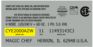
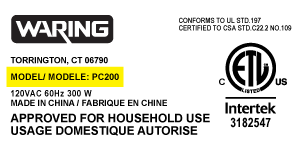
Model numbers can be made up of numbers (1005400, for example) or a combination of letters and numbers (LAT1000AAE). The model number will most likely appear on either a paper sticker or a metal plate. Your appliance's model number tag may look similar to the sample model number tags shown here (model number highlighted in yellow):
Model has been saved to My Models. If you're not signed in, your lists are available on this device and will expire within 30 days.
Model has been saved to My Models.
This is a grease filter, and it works with your range/stove/oven. This part is chrome-colored and measures 16.5 inches long by 9 inches wide. It is made of metal and is intended for use with downdraft...
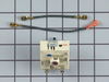
This is the replacement surface burner switch for your range. It measures approximately 1.5 inches by 1.5 inches, with a shaft that is approximately 1 inch long. The surface burner switch turns the su...
This bottle of non-abrasive cooktop cleaner breaks down and gets rid of the hardest baked-on stains and residue without causing any harm to your appliance. The bottle is 10 oz and does not require a l...
The Dual Radiant Surface Element with Limiter is an essential OEM replacement part for ranges, designed to provide consistent heat to the cooking surface. This element features a dual radiant design, ...
Struggling with inconsistent oven temperatures? Our GE Electronic Oven Control Board might be the solution you've been searching for. Designed to closely monitor and skillfully regulate your oven's te...
This Whirlpool surface element, known as ELMNT-SURF, is specifically designed for the smoothtop range. This 8" element comes with a built-in overheat limit switch, ensuring that it delivers heat safel...
$142.32
In Stock
Order now and your part arrives by May 11
Questions And Answers for CVE3401Q
Be the first to ask our experts a question about this model!
✖
Ask a Question
Ask our experts a question on this model and we'll respond as soon as we can.
Remove Ceran Galss top by removing hex screws below the rim. Also remove the two opposing screws in the center of the downdraft opening. Ceran top comes off easily now. The instructions with the new switch were very poorly written, so here is how I got the new switch to work: Attach the black wire(s) from the old switch (termi
... Read morenal 2) to the new switch terminal P1. Also attach the jumper cable to P1 and "jump" it to S1.
Attach the orange wire (old switch terminal 5) to S2 Attach the yellow wire (old switch terminal 4) to 4a Attach the tan/(white?) wire (old switch terminal 3) to terminal 4 on the new switch Attach the single red wire from the right front element to terminal 2 on the new switch. Attach the 'compound' red wires (the ones that come from the left rear/outlet connection and is also attached to the right rear switch) to terminal P2 on the new switch. There is no need to seperate the compound red wires as the instructions might lead you to believe. Good Luck
The repair itself was very easy. “How to connect” was very hard to get.
To get access to the switch, unscrew 2 screws from each side of front panel and then 4 screws from the bottom of it (open the door first). Have a box or a small table about 30” high to use it as support for the front panel.
The end result
... Read more(colors for the Right Front- R.F.- burner) : Old label -> New label
1. Double RED: N -> P2 (incoming power, Line 1) 2. Single RED: N -> 2 (to Inner AND Outer heating elements common wire) 3. Single BLK: L1 -> P1 (incoming power, Line 2) 4. Single TAN: H1 -> 4 (to the Inner heating element) 5. Single YEL: H2-> 4a (to the Inner heating element) 6. Single BLK: P -> S2 (to the R.F. indicator control light) 7. Attach jumper black wire (included with new switch) from P1 (P1 has two connectors close together) to S1.
Undid two screws on underside of cook top, lifted and exposed underside. Transferred wires from the faulty burner to the new burner, one at a time, paying close attention to their respective position on the wiring posts/terminals. Undid two screws holding old burner and then mounted the new burner to underside of cook top. Was really simp
... Read morele to do. :)