


 My Orders




CP320W Jenn-Air Grill - Overview

Enter a part description. DIY Heroes keep it simple, eg. "belt" or "pump".
Search filter:
Clear Filter
Your search term must have 3 or more characters.

$21.45
In Stock
Screw
Part #W11233072
This is a multi-use and multi-appliance screw. It can be used on a microwave, refrigerator, range/oven, air conditioner, dehumidifier, washer, or dryer. The measurements of this screw are 8 x 1/2 inch. It has 6 threads. Refer to the manual provided by the manufacturer for further information on repair and accurate guidance. Remember to wear work gloves as a safety precaution.

$78.26
In Stock
Surface Burner Switch - 240V
Part #W11120791
This surface burner switch, also known as an infinite switch, controls and regulates the heat output of the burners on a stovetop. The user simply adjusts the knob on the user interface panel, which in turn controls this switch. Made for various ranges, wall ovens and cooktops, this is a genuine OEM part that comes by itself, without any ...Read morehardware like screws or nuts. This burner switch is an electrical component that you also handle directly, so it can become faulty leading to problems like your stovetop not heating enough, overheating or staying at a fixed heat. This burner switch is a vital component for your stovetop and if it presents any of those issues, it needs to be replaced immediately. A screwdriver, set of pliers and wiring diagram will be needed for the replacement and installation process, and you will need to remove your appliance from the wall outlet first. Remove the knobs from the control panel and then gain access to the underneath portion of it with your screwdriver and disconnect the switch. Remove the wires from the burner switch with a set of pliers and disconnect the securing screws holding the switch in place. Now, you can install the new switch and reassemble the panel, being mindful of wiring each connector to the appropriate wire.
Read less

$81.04
In Stock
Grill Element
Part #Y04100124
This Grill Element from Whirlpool is a genuine OEM part specifically engineered for optimal compatibility with select models from trusted brands like Whirlpool, KitchenAid, Maytag, Jenn-Air, Amana, Inglis, and Magic Chef. Designed with four flat terminals along with a shunt (jumper) between two terminals, it offers a round ground terminal...Read more and is adjusted to exclude a shunt in certain models. Do check your original element for compatibility. This product may present small variations in size and shape, despite a similar appearance, hence we urge you to verify your model's requirements before your purchase. Choose this genuine Whirlpool grill element to ensure durability, efficiency, and the continued high performance of your appliance. Trust Whirlpool for your appliance part needs combining innovation, strength, and dependability.
Read less

No Longer Available
Air Inlet Grill
Part #71001673
This part is located over top of the blower in the center of the stove top.

No Longer Available
KNOB- INFI
Part #Y706096
$118.52
Special Order
USE WPL 5700M436-60
Part #12200018
No Longer Available
Motor Assembly
Part #700556
$7.47
Special Order
Screw
Part #WP71001171
No Longer Available
USE WPL 4369683
Part #706003
$8.55
Special Order
USE WPL 588550
Part #700450
No Longer Available
USE WPL 4153881
Part #706026
No Longer Available
USE WPL 4152969
Part #706061
Common Symptoms of the CP320W
How this model fails, and the parts that fix it.
Element will not heat
Fixed by
these parts
these parts


Show All
Will Not Start
Fixed by
these parts
these parts
Show All
Oven is too hot
Fixed by
these parts
these parts
Show All
Watch our pros, then fix it yourself.
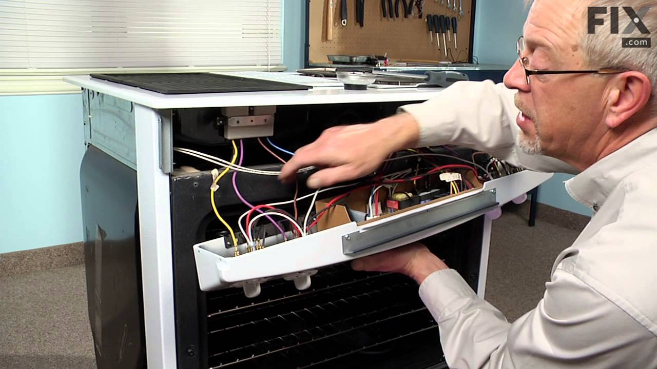
See how others fixed this model. Time, tools, difficulty, and steps that lead to victory!
View More