Enter the code TAKE10OFF at checkout to apply your discount. Discount will be applied at checkout when the code is entered & applies to all parts. Cannot be combined with any other coupon or special offer & cannot be applied to a previously placed order. Not valid toward tax or shipping & handling. Discount has no cash value. Discount expires on May 28 at 11:59pm EST.
You've Got 10% Off Your First Order!Save 10% with code at checkout *click to copy coupon code
Keep searches simple. Use keywords, e.g. "leaking", "pump", "broken" or "fit".
The part I ordered has 5 connections and the part to be replaced has 7 connections. I had to ask a friend who is expert in electrical wiring to help.
My friend used a tester to determine where each wire was supposed to connect to. I'm not sure what he did with the extra connections. Bottom line is this part should work but you need an expert to do it for you because it's, like I said, not exactly like the one to be replaced.
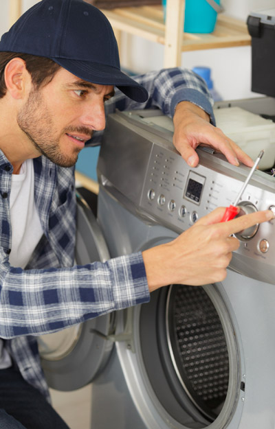
The bulb has a plastic clear cover. That cover can just be carefully removed using a screwdriver. It's held in by a metal bracket. After you remove the cover. You'll just need to replace the bulb and then re-install the cover and bracket.
my original part arrived and it did not fit. When I called to explain the problem I was told it was the wrong part. The big problem is... Frigidaire calls the receptacle a terminal block kit as well as a terminal block kit which is a totally different part. I tried to explain that to several different folks I spoke to at your company as well as Frigidaire but I'm not sure if I got that point across. Take a look at part # 530 393 5058 and part # 530 440 9888 and you will see that they both mention terminal block kit. Hopefully the part I am getting from Frigidaire is an OEM part and will fit.
The original instructions were to replace burner and plug wires back in the same plug they came from. The problem is that the plug order had changed between parts. Use a pencil to highligt the plug numbers on both new and old plugset, to fint the new plug positions. And need to reorient one of the burners to allow existing wires to reach.
unscrew the sensor inside the oven; took off the back of range to access harness of sensor; the replacement part harness did not match up to the original, so we stripped the clip from the end of the part and also the end of the harness in should clip into. after joining the wires together with ceramic wire nuts we tested the oven to make sure all worked AND IT DID!
Dual burner would only work on high and only the large burner worked
Replaced the dual infinite switch behind the panel. The wires were easily matched, even though the switch looked a little different. Works perfectly now.
Followed the parts select video. However there were differences. Four screws to release stovetop from brackets very difficult to break free even once correct bit identified. No spring clips but studded screw and coil springs let elements fall right off underside bracket. Need fours hands to hold back in place to screw bracket back in place to hold elements.
1. Loosened 2 sensor mounting screws and removed them. 2. Tripped range circuit breaker to off. 3. Pulled out the range but left gas connected. 4. Loosened the 4 screws on RH side of the top back panel and carefully pried that side of the panel open. 5. Using fingers, threaded the sensor's wiring harness through insulation and into the oven. 6. Unplugged old probe. 7. plugged in new probe. 8. tugged wiring harness back through insulation behind the oven. 9. Using 2 screws removed in 1 above, mounted new sensor. 10. Repositioned top back panel and fastened it in place. 11. Shoved range back in. 12. Tripped range circuit breaker to on. 13. Reset clock. 14. Set oven to 450 for test tun. 15.
Watching the video showed an easy, unscrew and screw back on process while connecting the wires back. It was really that simple. Once it was complete (not even 10mins), plugged it back in, and its been working great since.